This post—aside from being a praise of the Super-Fuzz circuit—is about a specific build that I finished by applying some irregular techniques on vero board. Why irregular? Because I was repurposing an enclosure that I had originally used to build a Ruby amp for a DIY talkbox. This enclosure had holes drilled on the sides for three knobs, and I was resolved to not let this box go to waste. And so I began to plan my first Univox Super-Fuzz DIY layout on vero.
About the Circuit
I never knew what I was missing from my life until the first time I plugged my bass into a Univox Super-Fuzz. Like most of the classics, the originals are super hard to come by where I live, so admittedly the first time I tried it out was after successfully building one (with the help of Storyboardist’s EffectsLayouts blog).
There are very few things that invoke the same feelings that were invoked that first time I ever plugged my bass into that Super-Fuzz. It was so familiar, as I had heard it many times before—but it was also electrifying, brutal, like a bolt of lightning. Its name is honestly perfect, but if I had to pick two more words to perfectly describe this circuit, they would be total and insanity.
There is no mistaking when this thing is on. This is not a circuit for those of us who are interested in mid to low gain overdrive tones. There is no gradual tuning control for the fuzz—there is simply always fuzz. The two controls on the classic module, Expander and Balance, are not quite the equivalent to the traditional Fuzz and Volume controls on your traditional Fuzz Faces and Tonebenders. Furthermore, the original module has a switch to toggle between tone capacitors. I favored the mods I’ve seen on Storyboardist’s blog based on FSB user Derringer’s mods. This includes a continuous Tone knob, two strategically placed ceramic caps between the collector and emitter of Q1 and Q6, and two internal trim pots which control the balance between Q4 and Q5 (supposed to be matched transistors) and the Germanium diode pair.
The Challenge
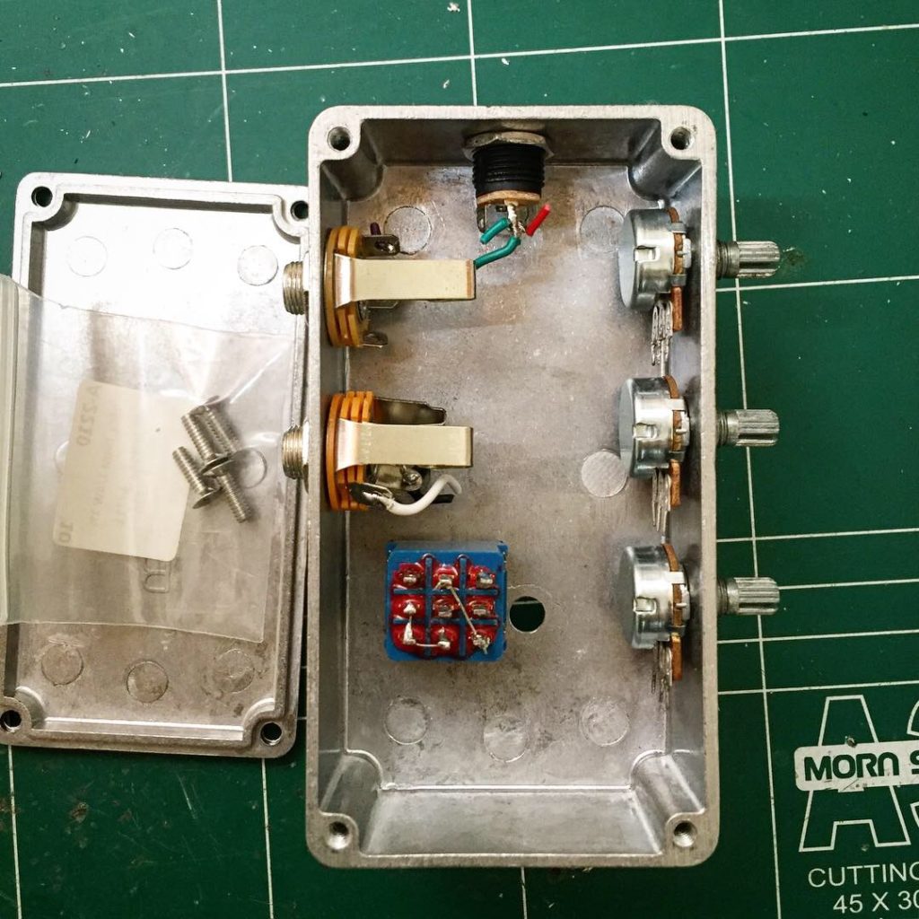
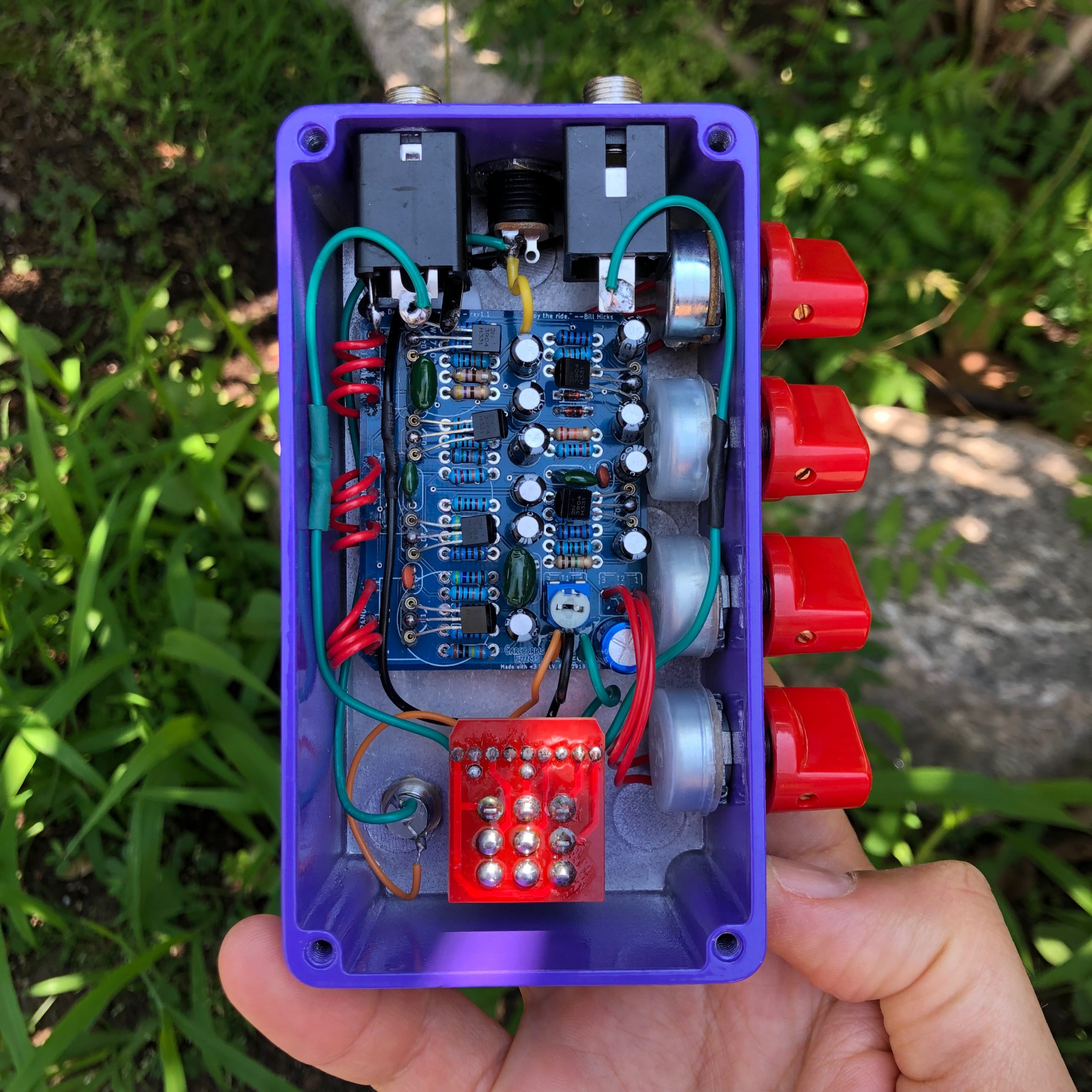
Given the space requirements and some calculations, I determined that the easiest fit would be to create a PCB that could be set up against the back sides of the potentiometers, with the components facing up towards the I/O jacks. Below is the layout I started with.
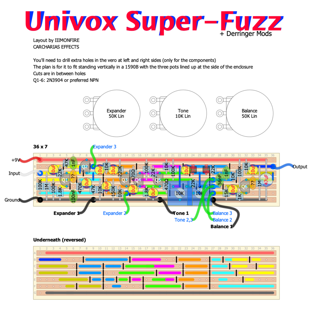
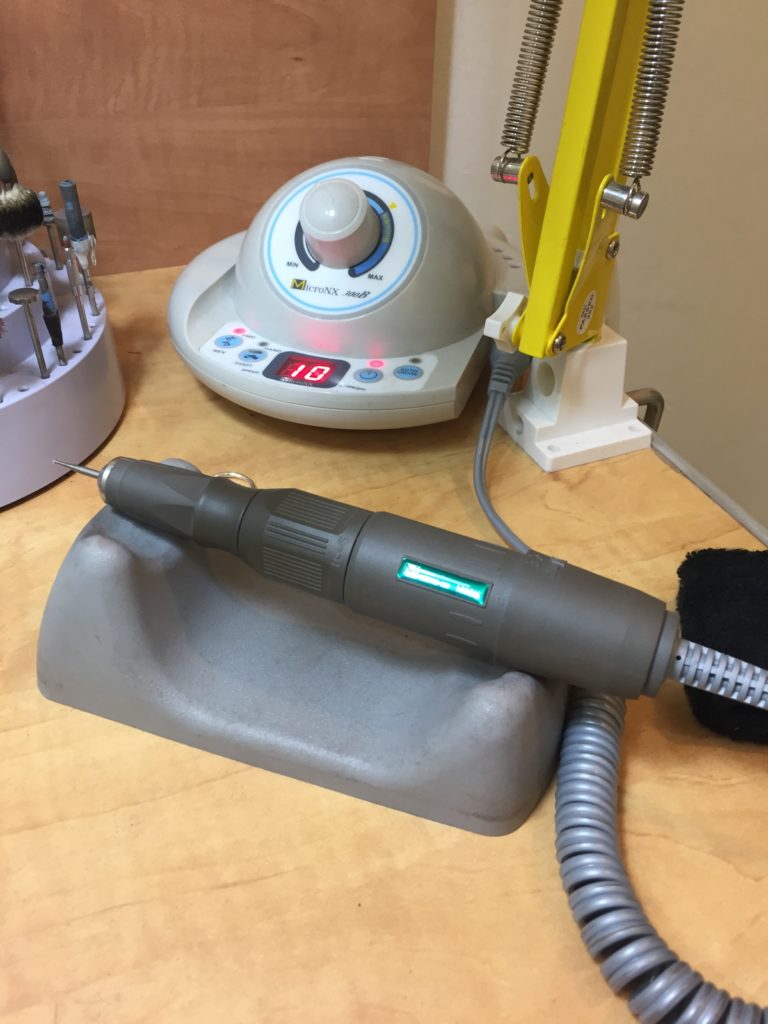
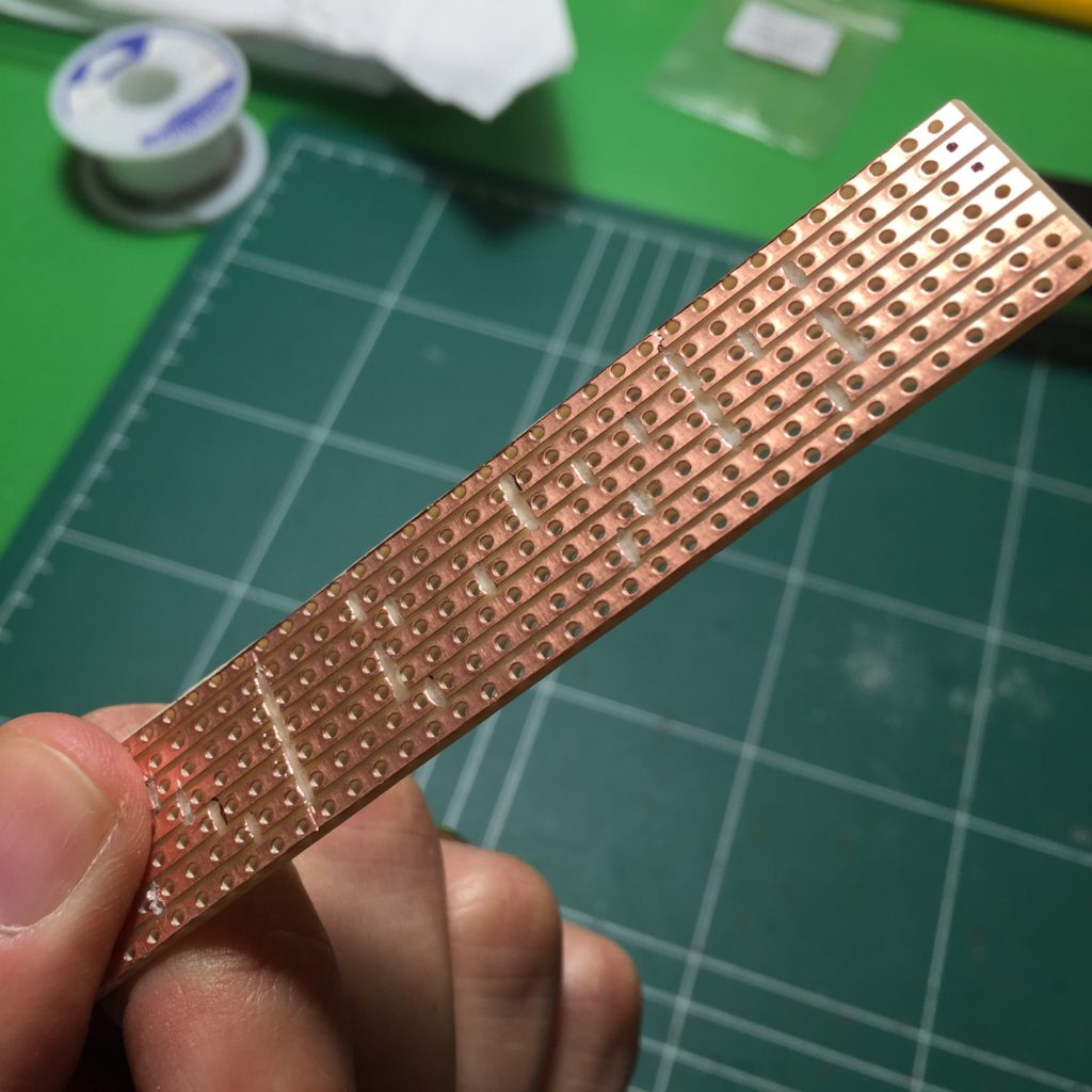
As a challenge to save space on the long piece of vero I chose, I needed to figure out a way to cut the vero strips in between adjacent holes, whereas up until then I would normally see vero boards where cuts are made directly on holes. To do this, I used a small motorized dremel—my wife happened to have one on-hand as she is a jewelry designer, and graciously permitted me to use it.
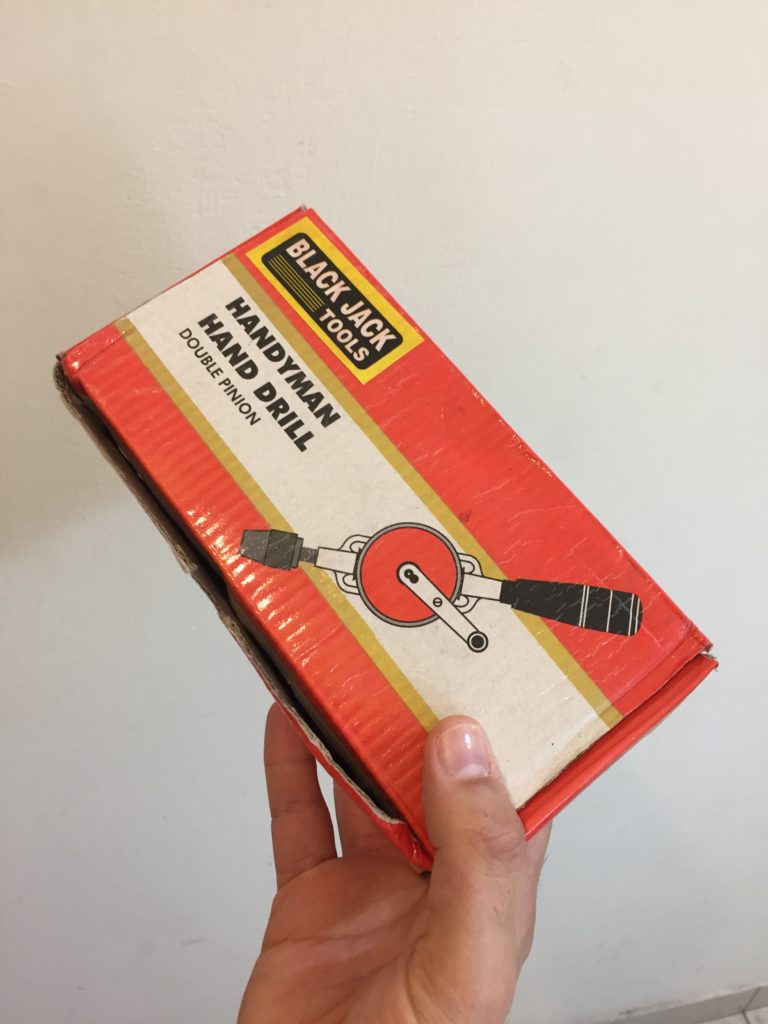
And there was another caveat—the vero board that I had at the time had only 34 holes for each strip, and I needed 36. Fortunately, we also had a small hand-drill for tiny holes (another jeweler’s tool that we had around).
It turns out that there is just enough empty space at the edges of the vero board to drill a tiny through-hole where needed. With all my manual work, here is what the vero board ended up looking like before being populated with components:
The Results
With the board now prepped, the rest of the story was fairly standard. I populated the board and tested it…

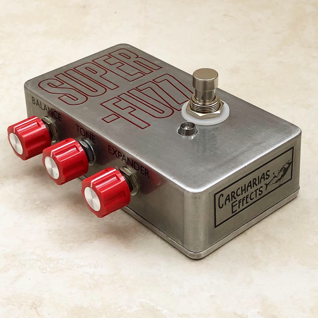
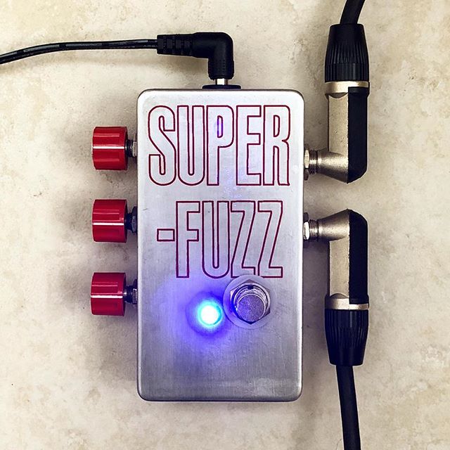
…implemented a simple graphic design, and voila! A great-looking Super-Fuzz for me to blow out all my super-fuzziest bass riffs on!

As always, if you want to build your own, feel free to follow the layout posted above and the instructions outlined in this post. You can also check out the aptly named Derringer Fuzz PCB available in the store, which includes the Derringer Super-Fuzz mods I’ve described above. You can see this PCB used in the Derringer Fuzz pedal which I built not longer after the DIY one above.